


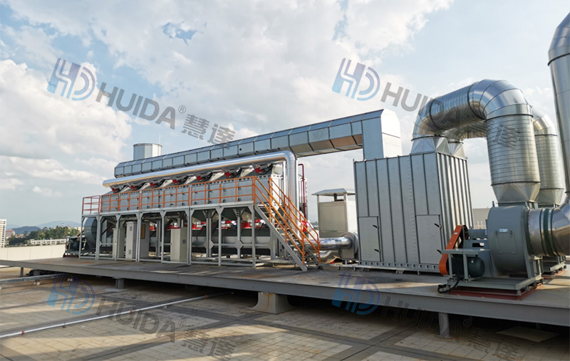
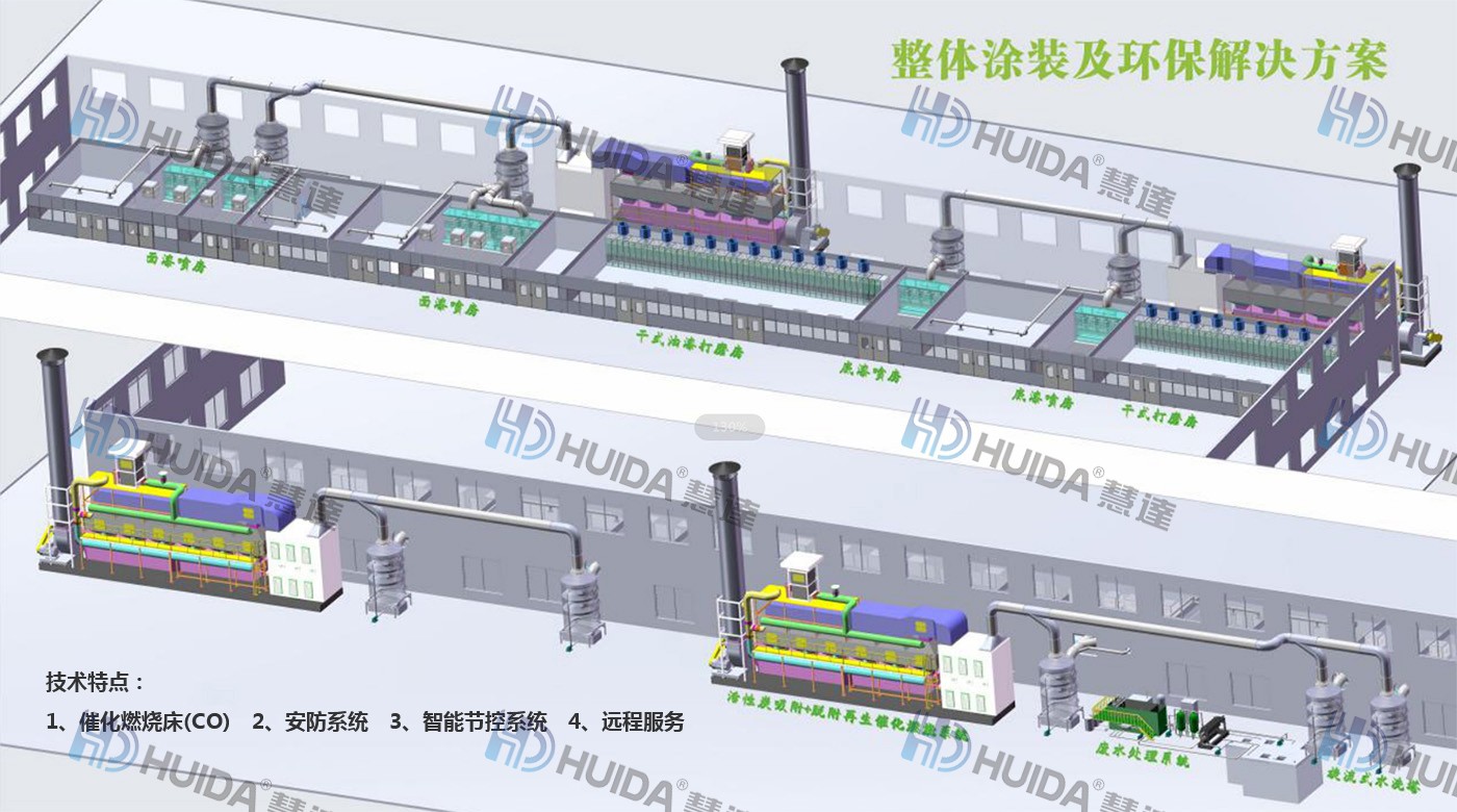
Catalytic combustion exhaust gas treatment system:
The catalytic combustion waste gas treatment system consists of activated carbon adsorption bed catalysis, combustion bed, adsorption air duct and valve, desorption air duct and valve, flame arrester, explosion and nitrogen protection system activated carbon, catalyst fan, control system, and exhaust chimney
Application field:
Adsorption recycling purification is suitable for the printing, electronics, coatings, rubber, and coating industries. The types of recyclable organic matter are as follows: hydrocarbons: benzene, toluene, xylene, solvent oil, naphtha, heavy aromatics, etc. Halogenated hydrocarbons: trichloroethane, dichloromethane, trichloromethane, carbon tetrachloride, etc. Ketones: acetone, butanone, methyl isobutanone, etc. Esters: ethyl acetate, butyl acetate, propyl acetate, etc. Alcohols: ethanol, isopropanol, butanol, etc.
Principle Analysis:
Activated carbon adsorption bed catalysis
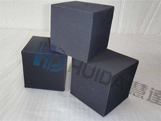
activated carbon
Water resistant honeycomb activated carbon, with a large specific surface area, strong adsorption capacity, low fluid resistance, and good regeneration effect;
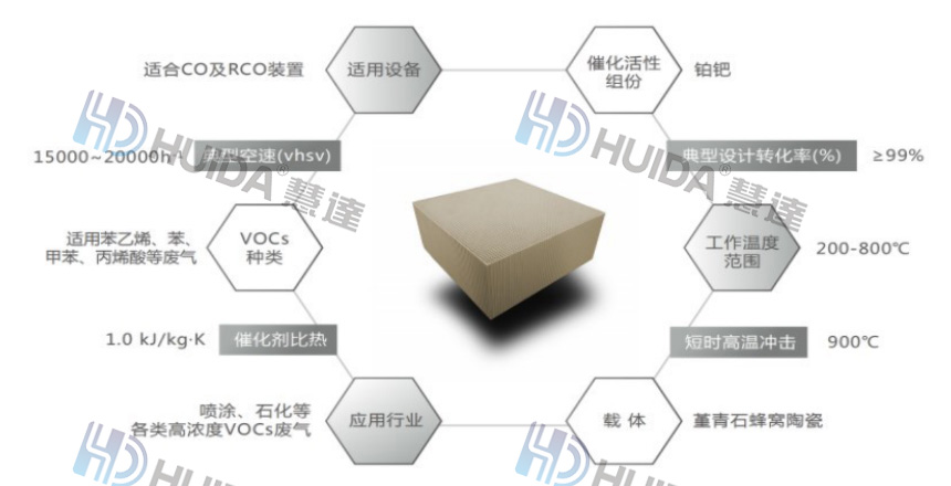
catalyzer:
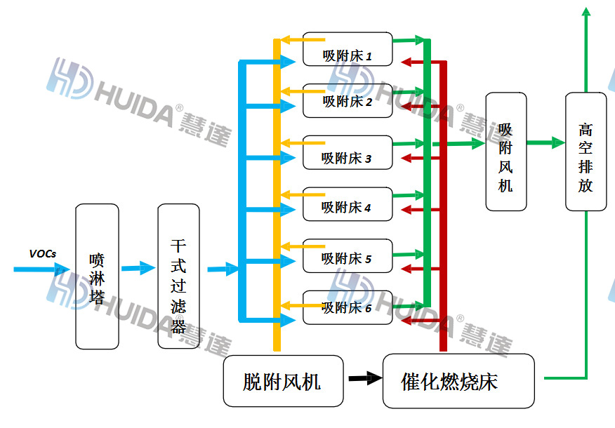
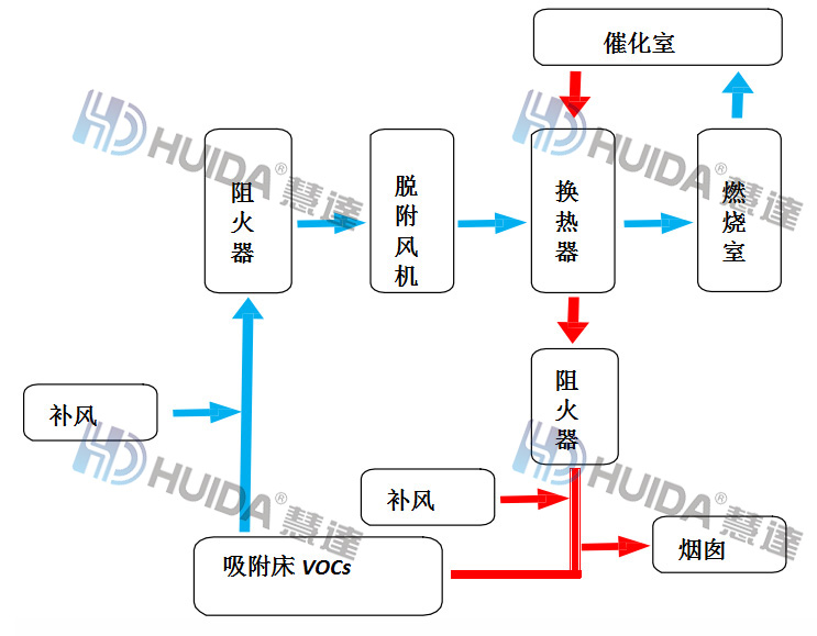
Process flow of activated carbon adsorption desorption catalytic combustion system:
By utilizing the adsorption force of microporous active substances on solvent molecules or molecular clusters, when the exhaust gas passes through activated carbon, the organic solvent in it is obstructed, thereby purifying the organic exhaust gas. According to the theory of molecular thermal motion, the adsorption bed heat energy is added from the catalytic combustion bed to increase the thermal motion energy of the adsorbed molecules or molecular clusters. When the molecular thermal force is sufficient to overcome the adsorption force, the organic solvent molecules compete with the adsorption system, resulting in the regeneration of activated carbon and the concentration of organic exhaust gas.
During the desorption of activated carbon, a portion of the heat energy generated after combustion is discharged into the atmosphere, and a portion is sent to the adsorption bed for the desorption and regeneration of activated carbon. This can meet the thermal energy requirements for combustion and desorption, greatly saving energy consumption.
When a certain adsorption bed is saturated and needs desorption regeneration, the PLC program automatically switches to the desorption working state. The desorption is completed, and the adsorption bed returns to the adsorption working state, thereby circulating desorption and adsorption
Process flow of catalytic combustion system
The exhaust gas in the adsorption bed enters the combustion chamber through a flame arrester and heat exchanger under the action of the desorption fan. When the temperature of the combustion chamber is heated to a certain temperature, it reaches the combustion reaction temperature of the exhaust gas. Then, through the action of the catalytic chamber, the exhaust gas is decomposed into carbon dioxide and water, and enters the heat exchanger for heat exchange with the low-temperature gas, causing the temperature of the low-temperature gas entering to increase to reach the required reaction temperature of the exhaust gas. The high-temperature gas is then heated into a gas of 150-200 ℃, which is discharged to the chimney after passing through the flame arrester, and a part enters the adsorption bed for activated carbon desorption and regeneration. This cycle works.
If the reaction temperature of the exhaust gas cannot be reached, the heating system will compensate for heating through an automatic control system to ensure the required reaction temperature of the exhaust gas in the combustion chamber, and the effective removal rate of the exhaust gas will reach over 97%. This system consists of catalytic combustion main equipment, fans, and electronic control system. The catalytic combustion main equipment consists of a heat exchanger, catalytic chamber, electric heater, flame arrester, and explosion-proof device. The flame arrester is located on the inlet and outlet air duct, and the explosion-proof device is located at the top of the main body
All rights reserved © 2021 Huida Environmental Protection Co., Ltd


 EN
EN CN
CN 86-769-2269 1302


